| |
RCL-Circuit
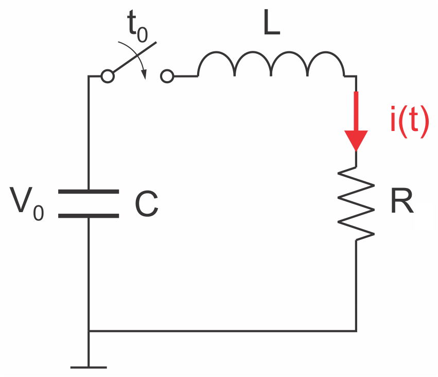
RCL-circuits (also often called RLC-circuits) are often encounterd in the description of the discharge characteristic of a pulse generator, especially for capacitors and including Marx-bank generators.
The challenge is to estimate peak current (and voltage) and how fast they could be achieved. Conversely, a comparison with measured outputs allows
in particular estimations on system-inductances. The tool will help to estimate current peaks and associated rise times. Voltage peaks can then be derived from the values of respective circuit elements
R and L.

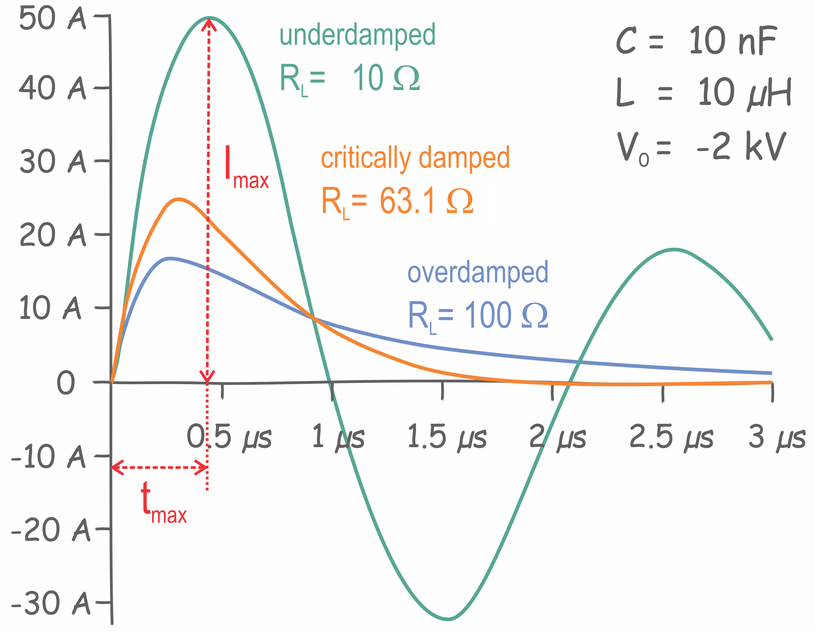
Current waveforms for underdamped, critically damped and overdamped parameters:

Underdamped solution (δ < ω0):
|
 |
 |
Critically damped solution (δ = ω0):
|
 |
 |
Overdamped solution (δ > ω0):
|
 |
 |
Solutions for the transient response when discharging a capacitance, C, through an inductance, L, and load resistance, R, can be found in respective textbooks.
In short: from Kirchof's law for the voltage along a closed loop, a second order differental equation can be derived. Depending on the solution of the characteristic
equation, the response can be described by either an underdamped, a critically damped or an overdamped solution.
Kirchhof's law for voltage loops:


Characteristic equation:

with resonance frequency (undamped natural frequency):

and damping attenuation:

and damped natural frequency:

or the "frequency" for the overdamped response:

Approach to Derive Solutions
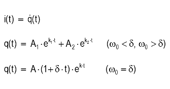
Ansatz:

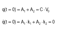
Boundary conditions:

|
|
|